Recovery
The Recovery page is for bench work on ECUs that are bricked or locked. Each module talks to the chip directly, independent of the normal K-Line/CAN connect flow.
Recovery works on the ECU off the car, with wires on its circuit board or debug pins. A wrong connection can damage the ECU. Only use this if you know what the points on the board are, and read the hint under the module list every time.
The modules are implemented, but the project's protocol list does not yet record any of them as tried on a real ECU. Treat them as untested.
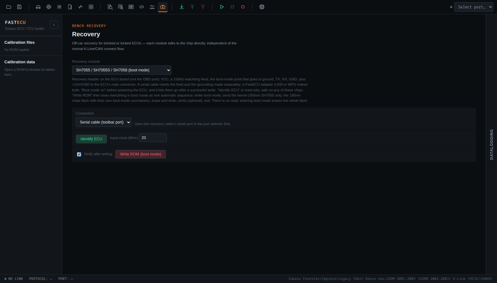
Choosing a module
Open Recovery in the toolbar and pick a module from the Recovery module list. The text under the list is a short wiring hint for that module.
The modules
| Module | What it does |
|---|---|
| MC68HC16Y5 (BDM) | A BDM pod on the chip's debug pins, with the ECU off the car. The pod can be an RP2040 board or a FastECU (ESP32) adapter over USB or WiFi, or a slower Arduino Pro Micro. With the RP2040 and ESP32 pods everything goes over BDM: reading and programming the ROM and TPU flash, with no separate kernel. A slower Arduino pod reads the ROM and TPU flash; it is not known whether it can do the writing reliably, so use the kernel route below for writing with it. |
| MC68HC16Y5 kernel (K-line) | A route for the slower Arduino pods only. Start kernel… in the BDM module starts FastECU's flash kernel, and this module then talks to it over a K-Line cable or J2534 device on the ECU's K-Line at 62500 baud: read, test write and write. The 12 V programming voltage comes from the ECU connector. You do not need it with an RP2040 or ESP32 pod. |
| Unisia Jecs UJ20 / UJ30 (boot mode) | 128 KB (UJ20) and 256 KB (UJ30) Unisia Jecs ECUs from 2000-2002. Through a K-Line cable or J2534 device (a FastECU adapter works over USB or WiFi). 12 V programming voltage on RTS and the MOD1 pin on DTR (J1962 pins 11 and 9). The kernel goes in through the M32R boot mode, then the ROM is written. |
| SH7055 / SH7055S / SH7058 (boot mode) | Uses a recovery header on the ECU board (not the OBD port): VCC, a 150 Hz watchdog feed, the boot-mode point that goes to ground, TX, RX, GND, plus +12 V and ground to the ECU's main connector. Identify ECU is read-only and safe on any of these chips. |
SH705x details
- A serial cable needs the watchdog feed and the grounding made separately. A FastECU adapter (USB or WiFi) makes both: press Boot mode on before powering the ECU, and the adapter lets them go after a successful write.
- Everything is done in boot mode, over the boot mode connection, as one automatic sequence: connect to the chip, enter boot mode, send the kernel (350 nm chips only), write the ROM, verify (optional) and exit or reset. The Write ROM (boot mode) button runs all of it, and Verify after writing is a tick box next to it. You do not switch to the normal K-Line connect flow on the ECU page.
- 180 nm chips (SH7055S, SH7058, SH7059D) have their own flashing code in boot mode, so no kernel is sent. 350 nm chips (plain SH7055) have the kernel sent as part of the same sequence.
- There is no Read ROM. Entering boot mode erases the whole flash by itself, so there is nothing left to read. Verification is only possible after a successful write.
- Identify ECU only asks the chip what it is. It is read-only and safe on any of these chips.
Have the ROM file you want to write ready before you start. If the write does not complete, the chip is left blank until you write again.
Where this fits
Normal reading and writing is on the ECU page's ROM tab. Use Recovery only when that route no longer works.
This is not ready yet. Check back later, or ask on the forum.