Injector scaling & latency
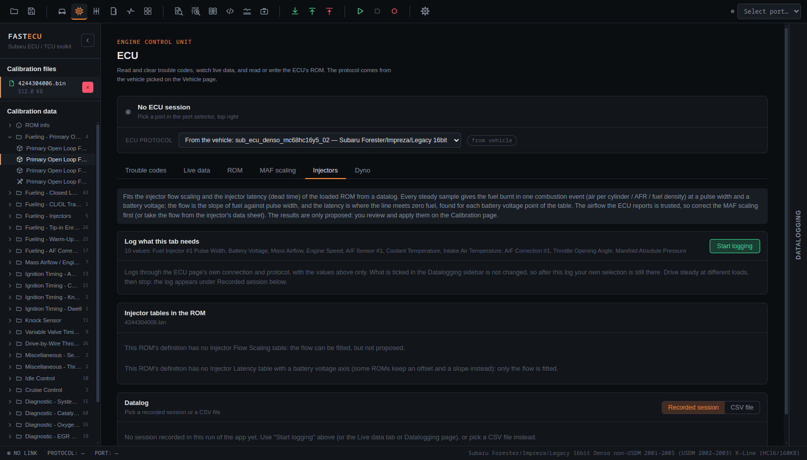
The Injectors tab fits the ROM's Injector Flow Scaling and Injector Latency (dead time across battery voltage) from a datalog.
Status
Run against datalog files and found to work. Not yet tested in real life (log, make the change, log again) to see how well the fit really performs.
Before you start
- Correct the MAF scaling first. This tab treats the MAF as correct.
- The datalog can be a recorded session, a log this tab starts itself with Log what this tab needs, or a CSV from your log folder.
How it works
- Every steady sample is one point: injector pulse width against the fuel burnt in a combustion event. The air per cylinder comes from the MAF reading and engine speed (or the calculated load), divided by the mixture and the fuel density. The mixture is the A/F sensor's reading, or stoichiometric in closed loop only.
- The flow is the slope of that line and the latency is where the line meets zero fuel.
- The latency is fitted per battery voltage point of the table, or as one shift of the whole curve. A point without data stays as it was, neighbours are smoothed, and the change per point is limited. Samples far from the line are dropped.
- You can set the fuel (petrol, E85 or a custom stoichiometric AFR and density), the number of cylinders and the filters.
Result and proposals
The tab shows the samples against the line the ROM implies and against the fitted one, and the latency curve before and after with the samples behind each point. Propose flow scaling and Propose latency queue the changes as proposals.
Limits to know about
- Battery voltage seldom leaves 13-14.5 V in a normal drive, so the shape of the latency curve needs a log with other voltages. The tab tells you when the samples cover less than a volt.
- A ROM whose latency axis is not battery voltage (some Hitachi tables) gets the flow only.